Programmed board from Electronic Production unit and produced 2 additional uC boards and programmed them
Programmed in C using avrdude and FabISP to download program
see Electronics Production pageProduced board from established design provided on class page.
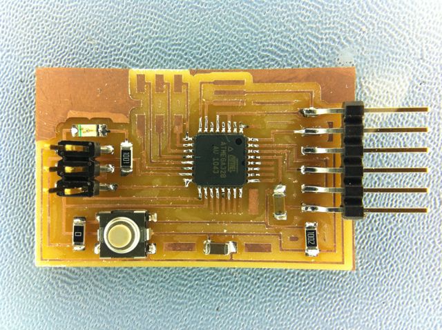
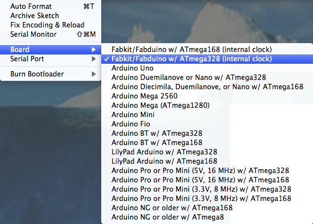
Didn't have tiny168 so used pin compatable tiny328
Modified Arduino boards.txt file to reflect fuse settings and bootloader needed for internal oscillator and 328 processor
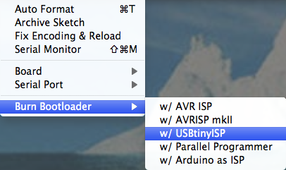
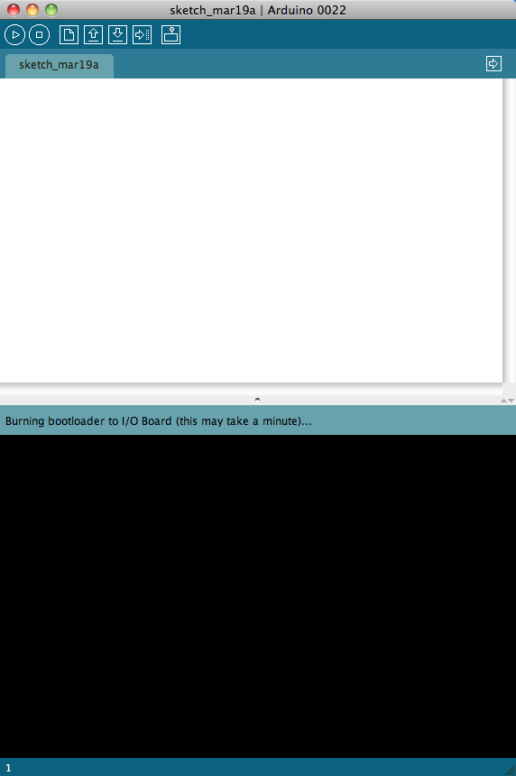
Loaded boootloader with Arduino IDE
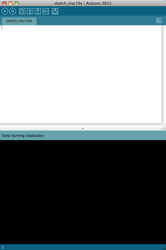
Ran variations of the 'Blink' sketch from Arduino IDE
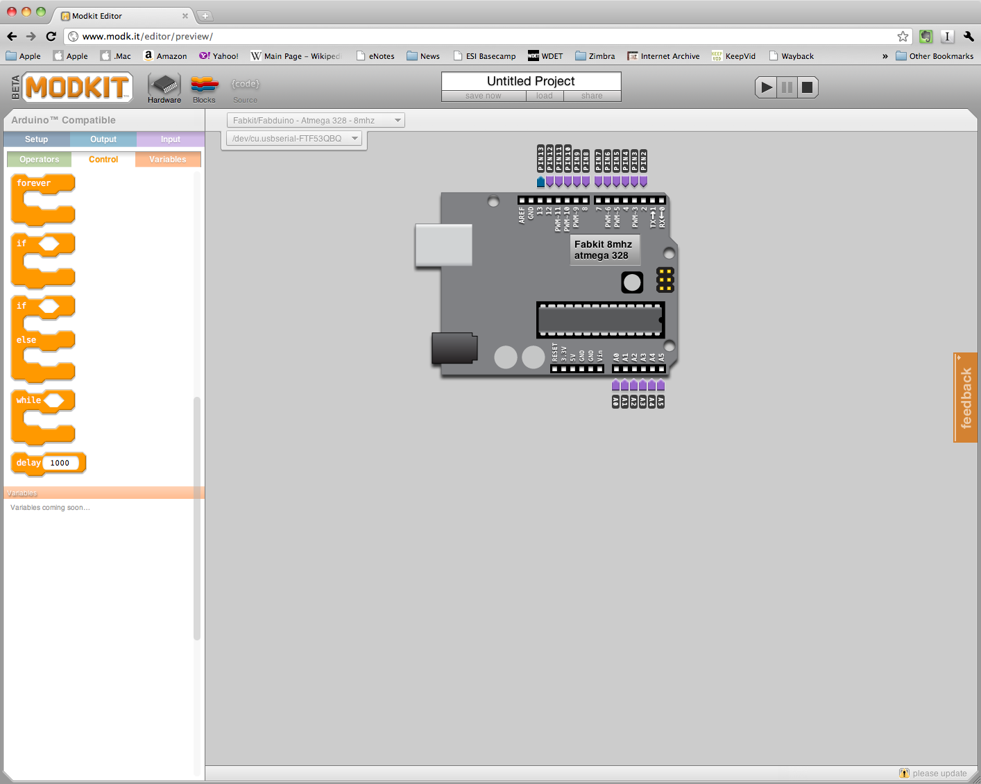
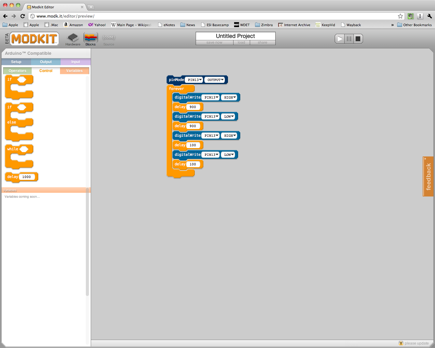
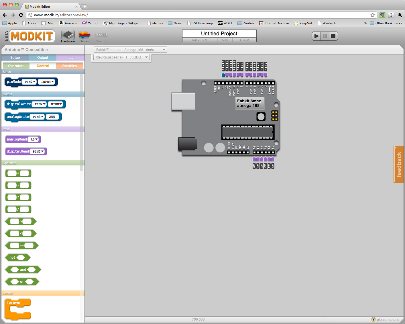
Programmed and ran Modkit programs with blocks to blink LED in various patterns
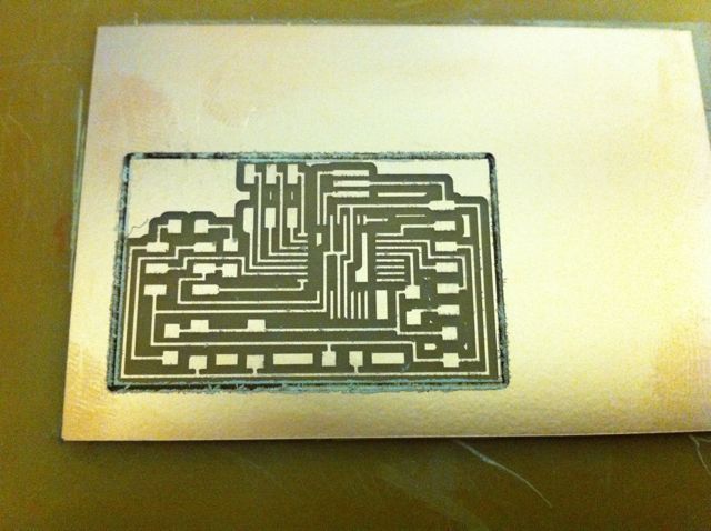
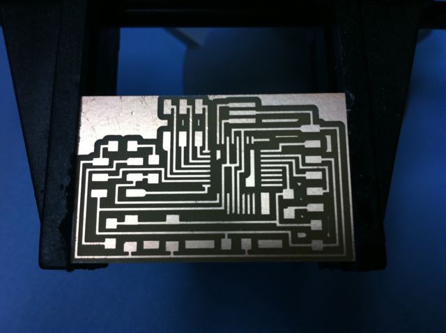
Produced board
Modified Arduino boards.txt file to reflect fuse settings and bootloader needed for resonator and tiny168 processor
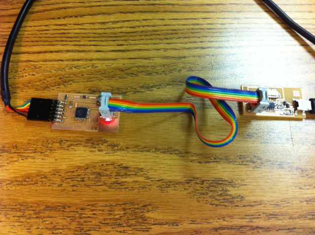
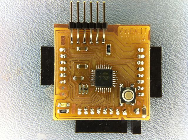
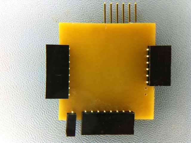
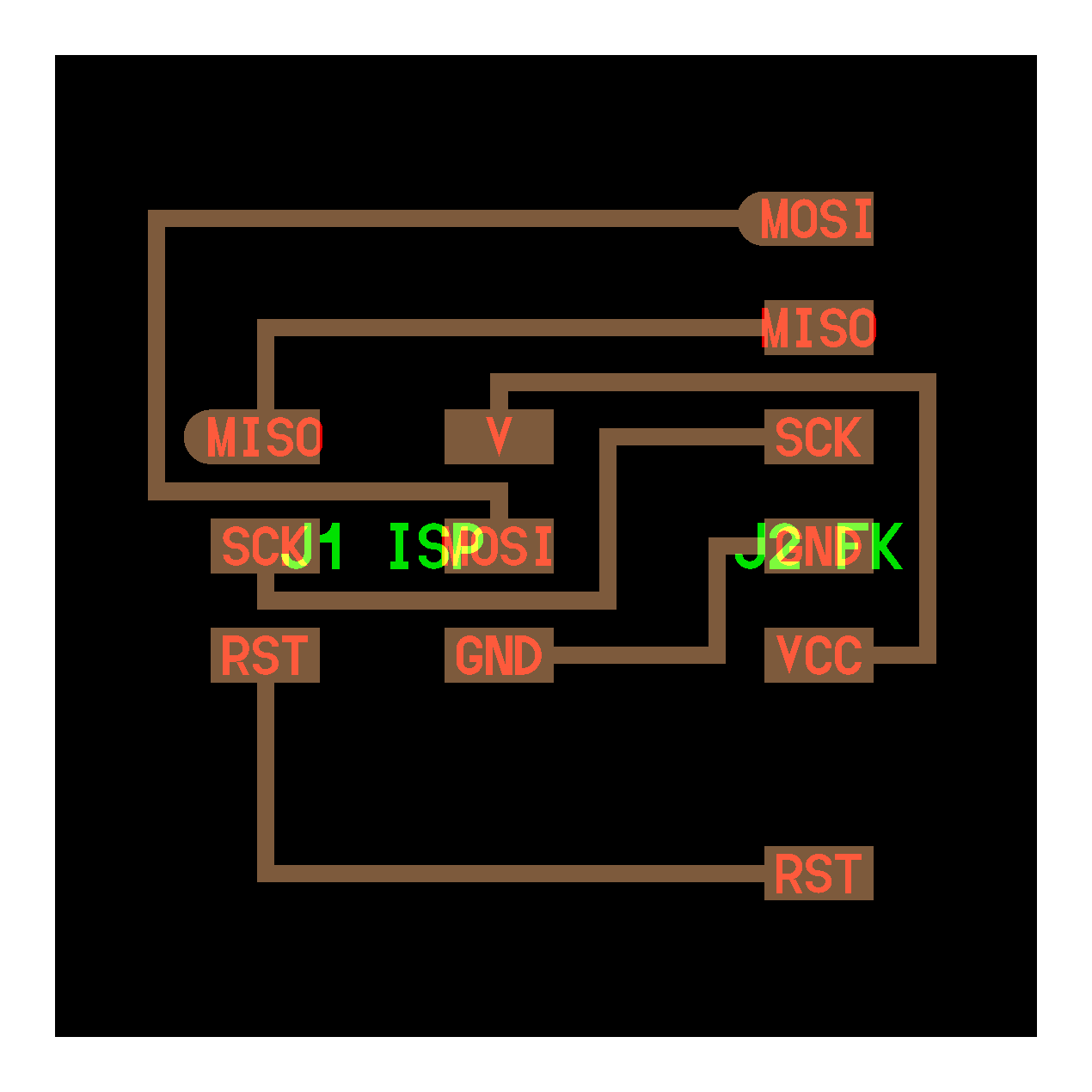
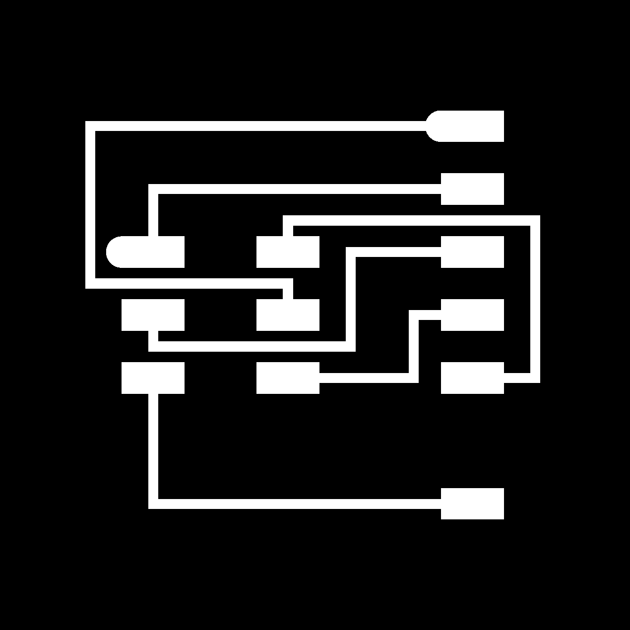
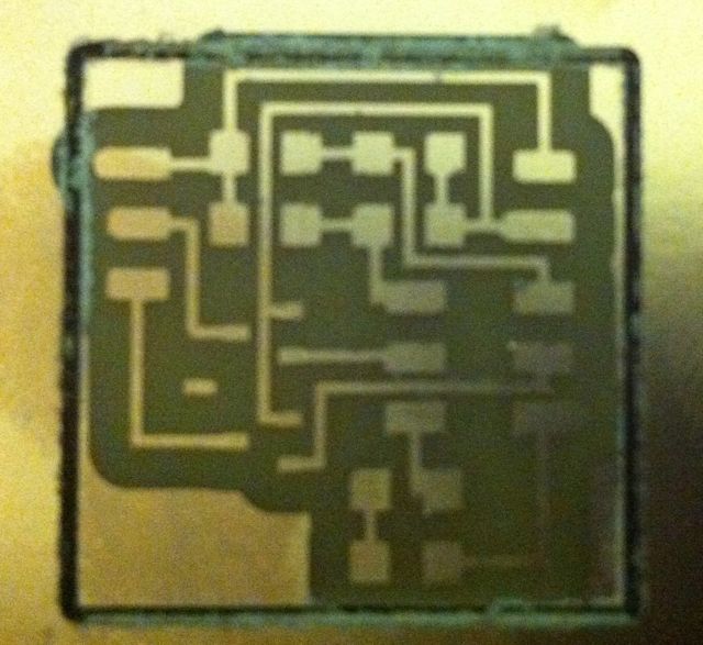
Designed and produced board to easily interface Fabkit to 6 PIN ISP connector. Used for initial bootloader programming with arduino IDE and subsequent direct C and assebly programming with avrdude

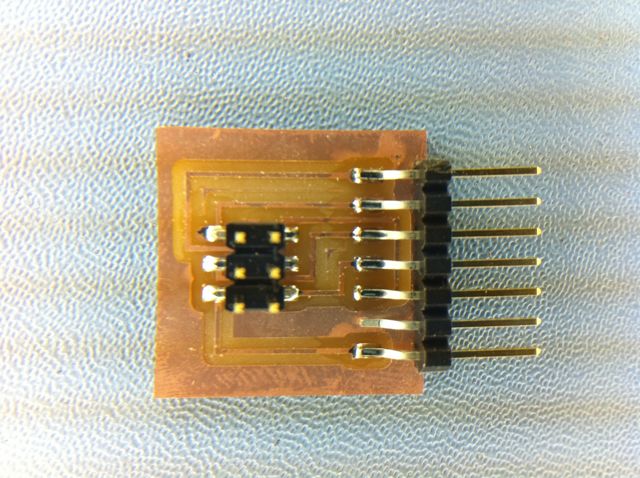
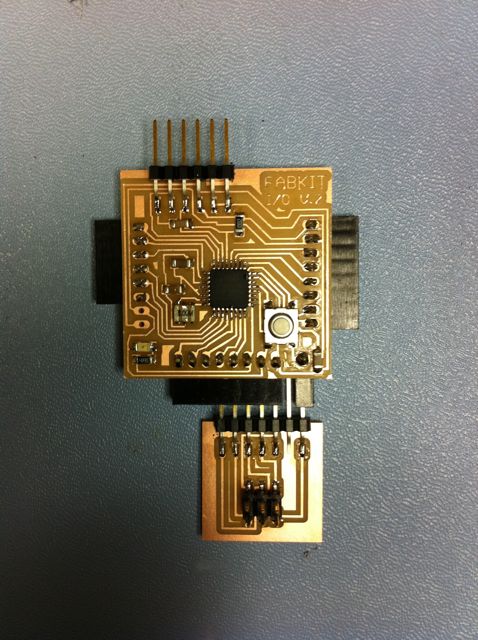
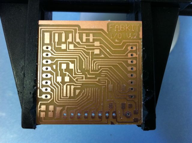
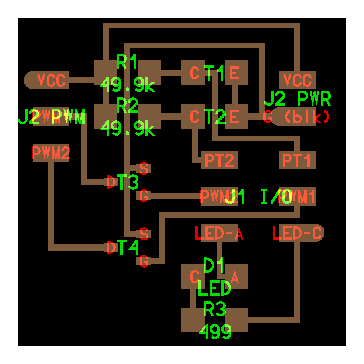
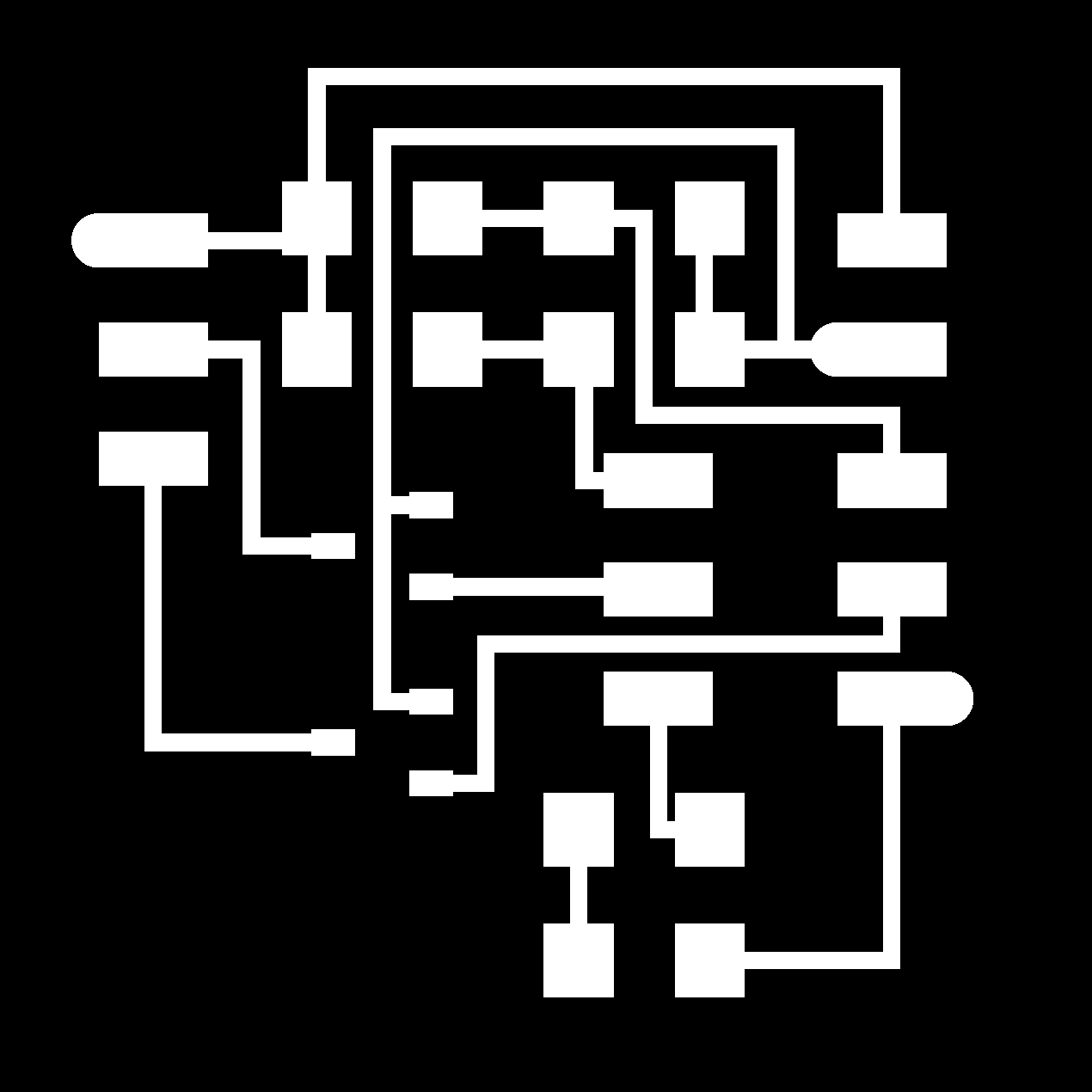
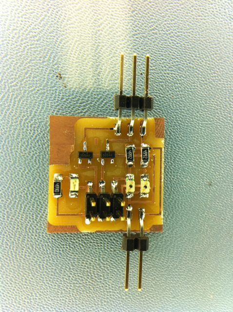
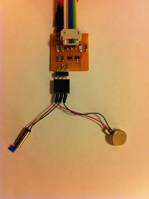
Designed and produced i/o board to test programming of LED input and output, 2 photodiode inputs and 2 PWM outputs with FETs for motor control

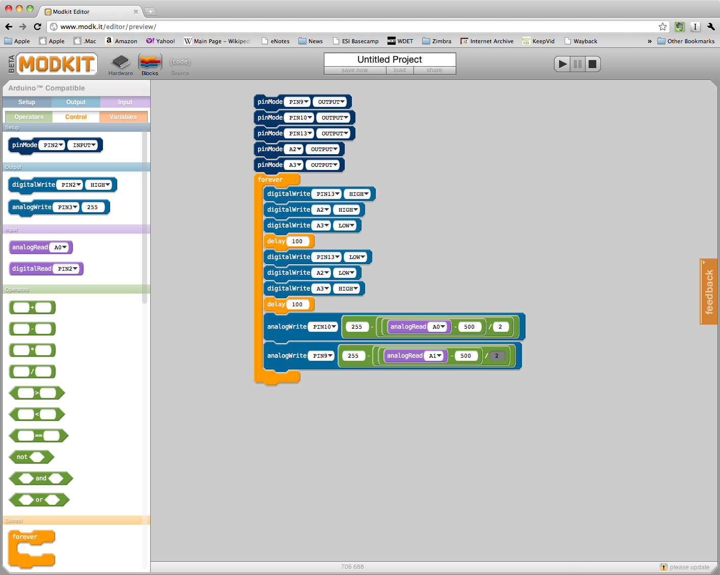
Programmed with Modkit blocks for LED output and photodiode inputs controlling PWM output for motors
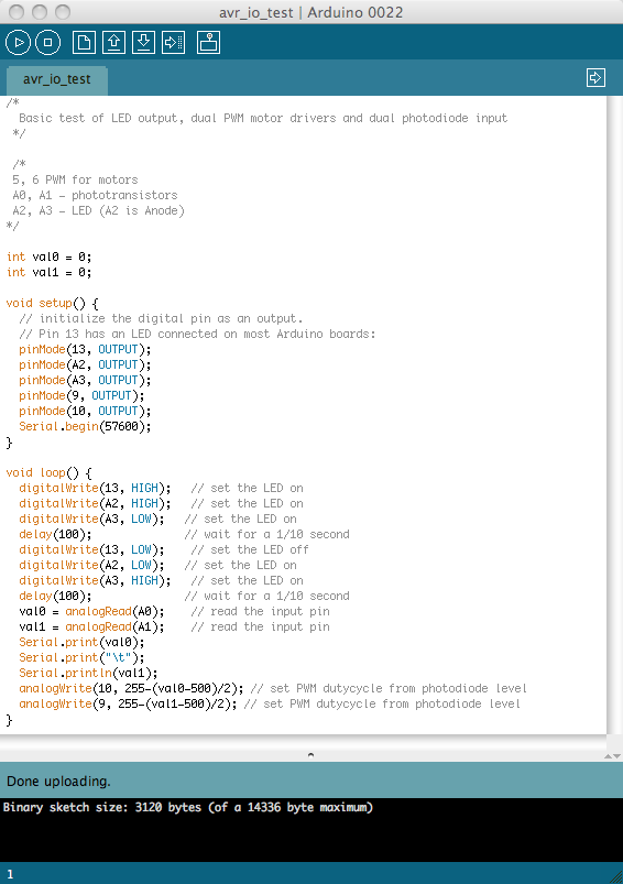
Programmed in Arduino IDE for LED output, photodiode inputs controlling PWM output for motors and serial output of photodiode measurements
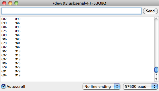
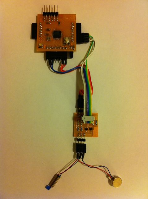
Quick video of Fabkit with i/o board running the sketches above. I am blocking the light to the photodiodes with an xacto knife. There are 2 motors connected to the PWM outputs. One is a normal small DC motor, the other has an offest weight mounted to the shaft to make it vibrate. Hopefully you can see and hear the speed of each motor change with the phototransistor controlling it.
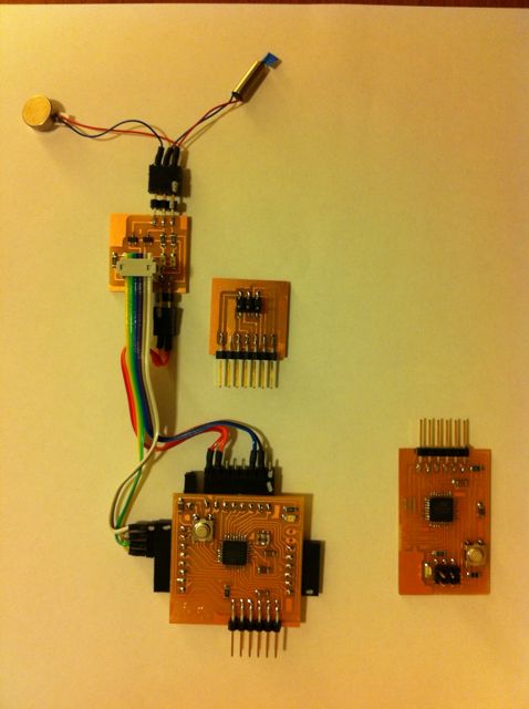
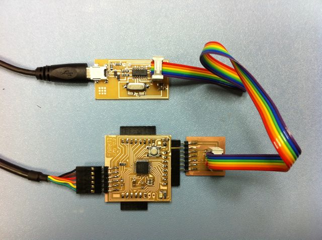
The boards produced and programmed this week.